Troubleshooting Manual
Attention! All Laars commercial and domestic use boilers should be installed and serviced by a professional service technician that is specialized in hot water boiler maintenance and installation and is Gas Safe Registered. Working on a gas appliance without proper qualification is prohibited by law and can cause various material damages. Faulty operation or/and installation creates carbon monoxide gas that will be present in flue gases and it causes serious injury as well as death. Installation performed by not qualified personnel will invalidate the warranty. Standard 5 year warranty is provided for most Laars models, and its registration need to be completed after installation at www.laars.com.
General Information
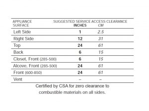
Laars Boilers are designed for indoor installations primary. Some models like Mighty Therm 2 (domestic use) Magnatherm, Neotherm, Neotherm LC, Pennant (commercial use) can be installed outdoor. When installing the indoor model following clearances should be provided (at minimum) in order to allow proper maintenance, service and inspection.
All Laars boiler models should be located on perfectly flat surface and in leakage free area, if that is impossible then proper drain pan should be installed under the appliance. Also all gas ignition system components need to be protected from water not only during the operation (rain, spaying,dripping, spraying, etc.) but also service (control replacement, circulator replacement).
Venting
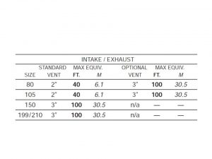
All Laars commercial and domestic use boilers require special venting system. Stainless steel and polypropylene venting system suppliers are not permitted for use with Laars appliances. We advice not to mix venting models and suppliers in venting systems. Laars boilers and water heaters must have provisions for combustion and ventilation air in accordance with the current local law regulations. Intake/Exhaust vent data is included in the table below
The Laars vent recommendations for installation:
- the vent pipe should be routed to the heater the most direct way
- all joints should be sealed and adequate hangers need to be provided per manufacturer’s instructions
- all venting horizontal system parts must be installed to prevent sagging, it is recommended not to keep any low sections that would be able to keep condensate
- the unit shouldn’t be install the way to keep the vent pipe weight. Table above shows for proper diameter vs. length allowed
- the vent pipe should be directed upward to the terminal, the dimension should be bigger tha 1/4” per foot to allow condensate drain
A single vent that is shared by multiple appliances has to be engineered by a competent venting personnel. Competent personnel should be able to choose the hardware, inducing equipment and controls. It s prohibited to vent Laars units unless the vent system meets this requirement. Laars appliances are never permitted to share a vent with Category I appliances.
Combustion
All Laars boiler appliances can take the combustion air either from the boiler location/room or the directly linked combustion air. In both cases there is a need for ventilation. If your boiler is installed the way it is taking the air from the room it is installed then this place should have an access to outdoors. If your unit is using the linked combustion then they shall be of the same cross-sectional area as the free area of the openings to which they connect.
Maintenance an annual service
For economical, functionality and environmental purposes your appliance you should be serviced annually. It most cases maintenance and annual service doesn’t take more than half a day on domestic boilers and full day on commercial models. Service specialist will verify, correct, replace following things:
- lubricate the system water-circulating pump
- clean the stainer if fitted
- verify the venting system for obstruction or leakage
- clean the screens in the vent terminal and combustion air terminal (when used)
- clean the appliance area
- verify low water cutoffs, flush float-type low water cutoffs
- verify and clean he condensate collection and the float switch
- verify that the condensate is being neutralized properly
- verify the flue passages, and clean with a brush or vacuum if necessary
- verify the vent system and air intake system, and ensure that all joints are sealed properly. If joints are used, those will be replaced with the new material
- in instances when maintenance service is performed because boiler won’t be in use for a longer period of time locations where freezing normally occurs will be isolated from the system and completely drained of all water.
Diagnostics
Diagnostics are used to check the status of the sensors and the digital inputs/ outputs. The diagnostics system also records a lockouts history and alarms. The system records the most recent lockouts or alerts. Current lockout will be displayed on the bottom of home screen. A “lockout” is a condition that will prevent the unit from starting or running. versus An “alert” that only shows a condition that is not normal. However if an alert persists the control system usually moves it into the lockout status. Analog sensors can be used to verify firing rate, operating temperatures, fan speed, etc. Digital Input/Output display can be used to determined status of different functions (usually on/off) like: pumps, valves, alarms, etc. Note that those values can’t be modified from the display level.
Fault codes
The two tables below includes a listing of the faults that might be generated by the controller, and displayed on the operator interface. Some fault codes can be remedied simple changing a parameter, while other more complicated faults and will require a qualified boiler personal to troubleshoot them. The first table lists the faults with its hold messages, second with the lockout messages.
Table 1. Hold/Alert fault codes applicable for all Laars boiler models
| Fault code | Error message | Solution |
| 3 | Internal fault- hardware fault |
Reset module. In instances when the fault repeats, replace module
|
| 4 | Internal fault- key feedback safety relay fault | |
| 5 | Internal fault- power (DC) output unstable | |
| 6 | Internal fault- clock processor invalid | |
| 7 | Internal fault- safety relay drive error | |
| 8 | Internal fault- no zero crossing | |
| 9 | Internal fault- bias flame out of range | |
| 12 | Internal fault- short relay safety drive cap | |
| 13 | Internal fault- PII (Pre-Ignition Interlock) shorted to ILK (Interlock) | |
| 20 | Internal fault- overflow and flame ripple | |
| 21 | Internal fault- sample mismatch flame number | |
| 22 | Internal fault- out of range flame bias | |
| 23 | Internal fault- since heating cycle starts bias changed | |
| 24 | Internal fault- stuck low or high spark voltage | |
| 25 | Internal fault- during flame sensing time spark voltage changed too much | |
| 26 | Internal fault- flame static ripple | |
| 27 | Internal fault- shorted flame rod to ground detected | |
| 28 | Internal fault- test linearity fails A/D | |
| 29 | Internal fault- bias flame is not settable in range | |
| 30 | Internal fault- shorted to adjacent pin flame bias | |
| 31 | Internal fault- electronics SLO error unknown | |
| 47 | Flame Rod to ground leakage | |
| 48 | Static flame (not flickering) H | |
| 49 | 24 VAC voltage low/high | Verify the module and display connections. Verify the module power supply and make sure that frequency, voltage and VA meet the specifications. |
| 50 | Modulation fault |
Internal sub-system fault. Review alert messages for possible trends. Correct possible problems.
|
| 51 | Pump fault | |
| 52 | Motor tachometer fault | |
| 61 | Anti short cycle |
Will not be a lockout fault. Hold Only
|
| 62 | Fan speed not proved | |
| 63 | LCI (Limit Control Input) OFF (Safety Chain Open) | Verify wiring and correct any faults. Verify Interlocks connected to the LCI to assure proper function. Reset and sequence the module; monitor the LCI status. If code persists, replace the part |
| 64 | PII (Pre-Ignition Interlock) OFF | Verify wiring and correct any faults. Verify Preignition Interlock switches to assure proper functioning. Verify the valve operation. Reset and sequence the module; monitor the PII status If code persists, replace the part |
| 67 | ILK (Interlock) OFF | Verify wiring and correct any possible shorts. Verify Interlock (ILK) switches to assure proper function. Verify voltage through the interlock string to the interlock input with a voltmeter. If steps 1-3 are correct and the fault persists, replace the part |
| 68 | ILK (Interlock) ON | Verify wiring and correct any possible shorts. Verify Interlock (ILK) switches to assure proper function. Verify voltage through the interlock string to the interlock input with a voltmeter. If steps 1-3 are correct and the fault persists, replace the part. |
| 70 | Wait for leakage test completion |
Reset module. In instances when the fault repeats, replace module
|
| 78 | Demand Lost in Run | |
| 79 | Outlet high limit | Verify wiring and correct any possible errors. Replace the outlet high limit.. When fault persists, replace the part |
| 80 | DHW (Domestic Hot Water) high limit | Verify wiring and correct any possible errors. Replace the DHW high limit. When fault persists, replace the part |
| 81 | Delta T limit | Verify pupm circuits as well as outlet and inlet sensors for proper operation. Double check the T Limit delta setting. When fault persists, replace the part |
| 82 | Stack limit | Verify wiring and correct any possible errors. Replace the Stack high limit. When fault persists, replace the part |
| 91 | Inlet sensor fault | Verify wiring and correct any possible errors. Replace the Inlet sensor. When fault persists, replace the modul |
| 92 | Outlet sensor fault | Verify wiring and correct any possible errors. Replace the Outlet sensor.When fault persists, replace the part |
| 93 | DHW (Domestic Hot Water) sensor fault | Verify wiring and correct any possible errors. Replace the DHW sensor. When fault persists, replace the part |
| 94 | Header sensor fault | Verify wiring and correct any possible errors. Replace the header sensor. When fault persists, replace the part |
| 95 | Stack sensor fault | Verify wiring and correct any possible errors. Replace the stack sensor. When fault persists, replace the part |
| 96 | Outdoor sensor fault | Verify wiring and correct any possible errors. Replace the outdoor sensor. When fault persists, replace the part |
Table 2. Lockout fault codes applicable for all Laars boiler models
| Fault code | Error message | Solution |
| 1 | Unconfigured safety data | New device, complete device configuration and safety verification. If fault continue replace module. |
| 10 | Internal fault- burner state control invalid |
Reset module. In instances when the fault repeats, replace module
|
| 15 | Internal fault- relay safety test failed due to ON feedback | |
| 16 | Internal fault- relay safety test failed due to safety OFF relay | |
| 19 | Internal fault- safety RAM write | |
| 32-46 | Internal fault- key safety 0- 14 | |
| 53 | AC input phases reversed | Verify the module and display connections. Verify the module power supply and make sure that both frequency and voltage meet the specifications. Make sure that terminal 10, J4 and terminal 2 J8 VAC applications are connected properly |
| 59 | Internal fault- Mux pin shorted |
Reset module. In instances when the fault repeats, replace module
|
| 97 | Internal fault- mismatch A2D | |
| 98 | Internal fault- VSNSR tolerance voltage exceeded | |
| 99 | Internal fault- exceeded 28V voltage tolerance | |
| 106 | Flame lost in MFEP | Verify main valve wiring and operation, correct any errors. Verify the fuel supply. Verify fuel pressure and repeat turn down tests. Verify ignition transformer electrode, flame detector, flame detector siting or flame rod position. When the fault persists, replace the module |
| 107 | Flame lost early in run |
Verify main valve wiring and operation – correct any errors. Verify the fuel supply. Verify fuel pressure and repeat turn down tests. Verify ignition transformer electrode, flame detector, flame detector siting or flame rod position. When the fault persists, replace the module.
|
| 108 | Flame lost in run | |
| 109 | Ignition failed | |
| 113 | Flame circuit timeout | Flame sensed during initiate or off cycle. Produces a Hold for 240 seconds. If still present after 240 seconds, system will lockout |
| 122 | Lightoff rate proving failed |
Verify wiring and correct any potential wiring errors. Verify VFD’s (Variable-speed Fan Drive) ability to change speeds. Change the VFD. If the fault persists, replace the module
|
| 123 | Purge rate proving failed | |
| 157 | Combustion pressure and flame Off | Verify that there is no flame in the combustion chamber. Correct any errors. Ensure that the flame detector is wired to the correct terminal. Make sure the F & G wires are protected from stray noise pickup. Reset the module, if code reappears, replace the flame detector. Reset the module, if code reappears, replace the module |
| 158 | Main valve On |
Verify and correct terminal wiring of the main valve. Reset the module. If problem continue, module should be replaced
|
| 159 | Main valve Off | |
| 160 | Ignition On |
Verify terminal ignition wiring and fix where needed. If problem continue, module should be replaced
|
| 161 | Ignition Off | |
| 164 | Block intake On |
Verify wiring and correct any errors. Inspect the Block Intake Switch to make sure it is working correctly. Reset the module. During Standby and Purge, measure the voltage across the switch. Supply voltage should be present. If not, the Block Intake Switch is defective and needs replacing. If the fault persists, replace the relay module
|
| 165 | Block intake On | |
| 172 | Main relay feedback incorrect |
Reset module. In instances when the fault repeats, replace module
|
| 175 | Safety relay feedback incorrect | |
| 176 | Main relay On at safe start check | |
| 178 | Safe start check at safety ON relay | |
| 184 | HSI/ blower output setting invalid |
Verify parameters and iff needed manually reset module. If fault consists, electrical grounding need to be checked. If fault continue, replace module.
|
| 185 | Enable setting Delta T invalid | |
| 186 | Enable setting Delta T invalid | |
| 189 | Flame sensor type setting invalid | |
| 193 | Ignite failure delay setting invalid | |
| 200 | Light off rate setting invalid |
Vent Test
In instances where old boiler is removed and to avoid vent leakage there is a need for making sure that all remaining appliances connected to the remaining vent channel. Following steps needs to be taken to properly test the vent:
- Switch off all the other appliances that are connected to the common venting system
- Any unused seals in the venting system need to be sealed
- Visually check if there is no corrosion, visible blockage, leakage, any type of restriction and venting system is the proper size which could cause an unsafe condition like: close all building doors and windows and all doors between the space in which the appliances remaining connected to the common venting system are located and other spaces of the building; a summer fan exhaust shouldn’t be operated, turn all the appliances that were yet not linked to the common venting system; fireplace dampers should be closed
turn on all applicable exhaust fans and operate them at their maximum speed; - Turn on inspected appliance. The thermostat should be adjusted the way your appliances can operate continuously
- After approximately 5 min of appliance operation at the draft hood relief test for spillage should be done. Best is to use simple match, lighter etc
- After it verify that the all the appliance connected to the common vent are installed properly, tested these as outlined above, return fireplace dampers, doors, exhaust fans, windows to their original status
- Any improper operation of the common venting system should be corrected so that it obeys latest law rules.
Laars User Interface
The User Interface of most of the Laars boilers consists of two parts, button part and the display part. Display shows all current information about boiler status, messages from the SOLA controller and serve the purpose of being a good screen while setting up a boiler, while buttons serve the purpose of setting those values.
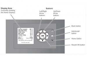
Buttons functionality:
- Info/ Install button- should be used for getting into the sub-menus, allows and monitor the controller set up
- Home button- should be used to go back to the Home display
- Left/ Right arrow buttons- should be used to for choosing the options, OK button needs to be pressed afterwards
- Up/ Down arrow buttons- should be used to for choosing the options, OK button needs to be pressed afterwards
- Back button- should be used to go back to the previous display
- Round OK button- should be used to confirm a value or action. Attention OK button on the displayed keyboard monitor is not the same OK as the Round OK button on the display
Navigating Users Interface and setting up the display area is pretty easy. You should always start from choosing the The Info/Install button, then choose or/and set the paramenters you want and press Round OK button. The arrow keys should be used for moving within the menus with the caution that the Back button gets you back to the previous screen, while the Home button gets you back to the main Home Display. Home display is shown on the picture below
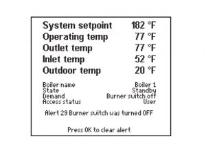
The Home Display consists of three parts:
- the upper part displays current boiler operating status like operating temperature, outdoor temperature, system set point, outlet and inlet temperatures for the water entering and leaving the boiler
- central part display additional operating and setup information like boiler status, name, access status and demand
- lower part displays any current holds, lockouts and alerts.
How to customize your home display?
In order to customize your home display follow the steps below:
- Press Info/Install button
- Scroll to highlight Display Setup and confirmed with pressing OK
- Highlight the line you would like to change, confirm with pressing OK
- Scroll to highlight the parameter that you do want displayed and then confirm pressing OK
- The new parameter is now displayed on the Home Display
- Repeat this step for the other parameters,
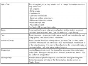
How to change control setting info?
In order to change control setting info follow the steps below
- Press Info/Install button
- The display will change to show the six sub-menus available
- Highlight the line you would like to change, confirm with pressing OK
- Table below shows all the functions available in each sub-menu
- Choose the function and confirm by pressing OK
Adjustable High Limit set up
The absolute high limit setting for the water outlet temperature for this unit is set at the factory to 90.5°C.Your appliance can use adjustable or lower limit setting, if you set it to do so. Use the down and up buttons first to select the right function and then down and up buttons to select the new settings. New settings should be confirmed by pressing OK button
Adjustable Stack Limit set up
The absolute high limit setting for the stack for this unit is set at the factory to 90.5°C. Your appliance can use adjustable or lower limit setting, if you set it to do so. Use the down and up buttons first to select the right function and then down and up buttons to select the new settings. New settings should be confirmed by pressing OK button
Filling the Boiler System
In order to correcty fill in the boiler system following steps should be taken:
1. Completely connect the system. Close all bleeding devices and open the make-up water valve.
2. Let the system fill slowly for several minutes
3. Where a make-up water pump is fitted the pressure switch on the pumping system should be adjusted in order to provide a minimum of 12 psi (81.8 kPa) at the highest point in the heating loop
3. In instances where a water pressure regulator will be provided on the make-up water line, the pressure regulator should be adjusted to provide at least 12 psi (81.8 kPa) at the highest point in the heating loop
4. Bleeding devices located on radiators units (all radiators all devices) should be opened
5. In order to remove all air from the heat exchanger you should cycle the boiler pump on and off 10 times, 10 seconds on and 10 seconds off
6. Run the system and appliance pumps for a minimum of 30 minutes with the gas shut off
7. Open all strainers in the circulating system, check the operation of the flow switch and check for debris
8. Re-check air bleeders (all)
9. Start up the boiler. Operate the entire system for minimum one hour, that should include boiler, radiation and the pump.
11. Shut down the entire system and vent all radiation units and high points in the system piping
12.The make-up water valve should now be closed and the strainer located in the pressure reducing valve needs to be checked for debris or sediment
13. Re-open the valve for make-up water
14. Check the water level in the system and check the water pressure. Your system is ready for normal operation when the water is at the highest point in the circulating loop
15. Prime the condensate trap with water
16. After placing the unit in operation, the ignition system safety shutoff device must be tested. To test you you should shut off the manual gas valve, and call the unit for heat. The main gas terminals will be energized, and attempt to light, for four seconds, and then will de-energize. Then the unit should go into lockout after the required number of trial for ignition periods. After this turn the power Off, and then On again. Press the manual reset button on the boiler control, open the manual gas valve, and allow the unit to light. While the unit is operating, all manuals gas valves need to be closed and the power in the main gas valve should be cut off
17. Within the first three days after the system start-up, verify the status of the expansion tank and air bleeders (all)
Freeze Protection
All Laars boilers are certified for indoor, some models- especially commercial use are certified for outdoor use. If you live in the area where there freezing is observed you need to take precautions to protect your appliance and pipes from freezing. Failure of system components, power outage, interruption of gas supply, activation of safety devices can stop boiler from normal firing. If boiler is located where freezing exists and appliance can’t fire and/or you observe that there is no water circulating in the system water may have freezed either in the appliance’s system or/and in the pipes. When water freezes, it expands which may result in bursting of pipes and damage to the boiler, which could result in leaking or flooding conditions. Remember not to use the automotive antifreeze. To help prevent freezing, Laars recommends the use of inhibited glycol concentrations between 20% and 35% glycol. Typically, this concentration will freeze protect till temperatures reach-20°C. If temperatures are expected to be lower than -5°F (-20°C), glycol concentrations up to 50% can be used. When concentrations greater than 35% are used, water flow rates must be increased to maintain a 20°F to 25°F temperature rise through the boiler. Laars supplied pumps are not all capable of maintaining the reduced temperature rise required with glycol concentrations greater than 35%. If glycol concentrations required are greater than 35% a field supplied pump should be used. Take into consideration that different glycol products provide various levels of protection. Also if you don’t maintain those products properly in the system, glycol products will become ineffective after a certain amount of time.
Boiler manual restarting
To manually restart your appliance you should follow the following step
1. Turn off the main electrical disconnect switch and isolate the appliance
2. All manual gas valves should be closed
3. wait 5 to 10 minutes till the boiler cools down
4. Set the aquastat or thermostat to its lowest setting
5. Open all manual gas valves
6. Reset all safety switches (manual reset high limit, pressure switch, etc.)
7. Set the temperature controller to the desired temperature setting, and switch on electrical power
8. The burner will go through a prepurge period and ignitor warm-up period, followed by ignition.
Appliance shut down
To properly shut down the appliance you should follow the steps below
1. The main electrical should be tuned off and the electrical switch should be disconnected.
2. All manual gas valves should be closed
3. In instances where your appliance might freeze drain it. Remember to remove all water from the heat exchanger, otherwise it may damage. Protect the pipe coming in the building from freezing.
Gas supply and piping requirements
Gas piping need to be supported floor stands or proper hangers. Appliance is not designed to support it. Most Laars models will operate normally without the use of high altitude modification at elevations up to 3050 m, but the gas pressure should never exceed 3.2k Pa. The minimum inlet gas pressure is 1.0kPa. Your boiler together with all other appliances that share the same gas supply line gas supply line operate at its maximum in order to check correct inlet supply pressure. You can check the supply pressure at the gas valve supply pressure port. If you observe lower than usual gas pressure you can suspect undersized gas supply lines, meter or in simply blockage in the gas supply line. Some Laars appliances are equipped with high and low switches for gas pressure that. Those switches are vent limited- integrally and don’t require any kind venting to atmosphere.
Condensate Drain
A condensate drain trap is built into all Laars boilers. The boiler drain need to be connected to the floor drain, condensate pump by a a 3/4” PVC pipe. The condensate drain purpose is to prevent accumulation of condensate. In instances where condensate pump won’t be used, the tubing needs to slope downward continuously towards the drain, no spiraling should be used. Condensate has a pH=5 which makes it a bit acidic and that cause a damage to some floor metal drains.
Warranty claims
Remember that all warranty claims for boilers still covered by it should be made at www.laars.com. When claiming a warranty please prepare model name and its serial number (information on the boiler’s rating plate), installation date, and installer’s name. Shipping costs are not included in the warranty coverage.